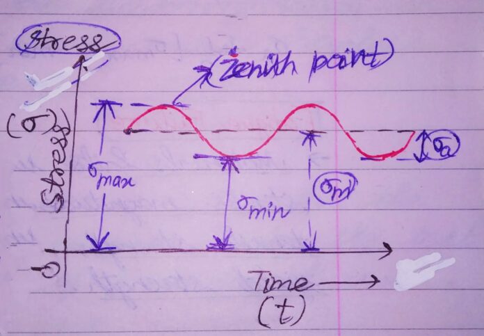
LIMIT DEFINED FOR FLUCTUATING STRESSES : ENDURANCE LIMIT
Limit of Fluctuating stresses
All components subjected to fluctuating stresses contains a Max. Stress Amplitude value for which it completes infinite cycles(106) of revolutions. This max. value of Stress Amplitude with a definite magnitude gave us concept of ENDURANCE LIMIT(E.L)
“{E.L}-APPROXIMATE ESTIMATION”- NECESSITY OF THIS BIG STEP:
Laboratory method of determining Endurance Limit of materials ,although being precise ,was also time consuming and long termed process. Also, a single S N CURVE to plot required many no. of tests on the material . So, finding endurance limit {E.L} for each and every material became difficult.
To solve this issue, approximate estimation of E.L ( Endurance Limit) taken in design.
This always come in use when experimental data of E.L are not given.
STUDY OF ENDURANCE LIMIT {E.L} AND APPLICATION OF THIS ANALOGY IN DESIGN :
Two Separate notations for Endurance strength used in this analysis :
Se‘= Endurance strength of a rotating beam specimen that subjected to reversed bending stress (N/mm2)
Se= Endurance strength of a mechanical component that subjected to reversed bending stress (N/mm2)
https://mechomotive.com/wp-admin/post.php?post=3674&action=edit
APPROXIMATE RELATIONSHIP BETWEEN Se‘ and Sut ( FOR VARIOUS MATERIALS)
| FOR STEELS | Se‘=0.5 Sut |
| CAST IRON AND CAST STEELS | Se‘=0.4 Sut |
| WROUGHT ALUMINUM ALLOYS | Se‘=0.4 Sut |
| CAST ALUMINUM ALLOYS | Se‘=0.3 Sut |
This difference in E.L values Se‘ and Se came due to a no of factors. These factors came due to working conditions specifications. For rotating beam specimen , there are standard specifications and working conditions which are fixed.
But , on the other hand, the actual component face different specifications and working conditions.
So, various factors came in study in order to compensate this effect. These factors are , therefore, called “derating” factors.
Derating factors : These factors have the duty to degrade or reduce the E..L of the standard rotating beam specimen until it matches with the test component’s E.L value.
DERATING FACTORS : IMPORTANT FACTORS TO BE STUDIED
1) SURFACE FINISH FACTOR ( Ka) :
Surface of rotating beam specimen polished to mirror finish. Final polishing done in axial direction to avoid circumferential scratches. The actual component is not so finished in surface terms . Here , stress concentration arises due to surface finish variations. Therefore, E.L values seems reduced here. The surface finish factor (Ka) now comes in action to compensate this reduction effect.
Ka values depends on the parameter of Ultimate tensile strength (Sut).
Therefore, as ultimate tensile strength increases, the Ka values decreases .
For finding Ka, refer to the chart given in DESIGN OF MACHINE ELEMENTS, V B BHANDARI .
2) SIZE FACTOR ( Kb ) :
The rotating beam specimen taken with fixed diameter (7.5 mm). It has been observed that larger machine parts induces larger flaw or fault chances in a component. This leads to stress concentration , and ultimately reduced E.L values.
Therefore , Kb values came in as to compensate the reduction between standard and practical values.
| d ≤ 7.5 mm | Kb = 1.0 |
| 7.5 mm < d ≤ 50 mm | Kb = 0.85 |
| d > 50 mm | Kb = 0.75 |
3) RELIABILITY FACTOR ( KC) :
The greater the likelihood of survival of a part, greater will be the reliability of a material.
The standard deviation of E.L tests is 8 % of the mean values.
The reliability factor ( Kc) used to achieve this reduction due to stress concentration effects on the material.
| RELIABILITY R (%) | KC |
| 50 | 1.000 |
| 90 | 0.897 |
| 95 | 0.868 |
| 99 | 0.814 |
| 99.9 | 0.753 |
| 99.99 | 0.702 |
| 99.999 | 0.659 |
4) MODIFYING FACTOR TO ACCOUNT FOR STRESS CONCENTRATION (Kd):
The reduction in E.L values are due to stress concentration. The stress conc. factor for cyclic loadigng found out to be usualkly lesser than the theoretical stress conc. factor.
So, a modifying factor is taken to account for this reduction . It is denoted by Kd.
Kd= 1/ Kf


