


STRESS have the same work in any force system; i.e to develop an Internal Resistance within the body.
FOR Different systems , there different nature of stresses developed.
1.NORMAL STRESSES DUE TO LOAD AND LOADING.
2. NORMAL STRESSES DUE TO BENDING
3.SHEAR STRESSES DUE TO TORSION
STRESS ANALYSIS IN VARIOUS LOADING CONDITIONS:
1. STRESS DUE TO LOADING (AXIAL AND TANGENTIAL)
ASSUMPTIONS IN ANALYSIS :
1. Material is homogeneous as well as isotropic.
2.Load is gradually applied.
3. There is uniform cross section as there is no area change.
4. There is no stress concentration due to const. cross section..
5.Line of action of force passes through the geometric axis of cross section (for axial loads)
1.FOR AXIAL LOADING : σT ∝ ε ⇒ σT = Eε (tension)
σC ∝ ε ⇒ σc = Eε (compression) E = MODULUS OF ELASTICITY/YOUNG’S MODULUS
2.FOR SHEAR LOADING : τ ∝ γ ⇒ τ= Gγ
G = MODULUS OF RIGIDITY
3. FOR HYDRO STATIC LOADING : p∝ Δv/v ⇒ p= k (Δv/v)
k = BULK MODULUS , p = pressure stress
*POISSON RATIO μ = (ΔD/D)/(ΔL/L)
RELATIONSHIP BETWEEN VARIOUS ELASTIC CONSTANTS
| 1. E= 2G(1+μ) |
| 2. E = 3k(1-2μ) |
2. STRESSES DUE TO BENDING MOMENT
A beam subjected to bending moment of magnitude Mb as shown below.
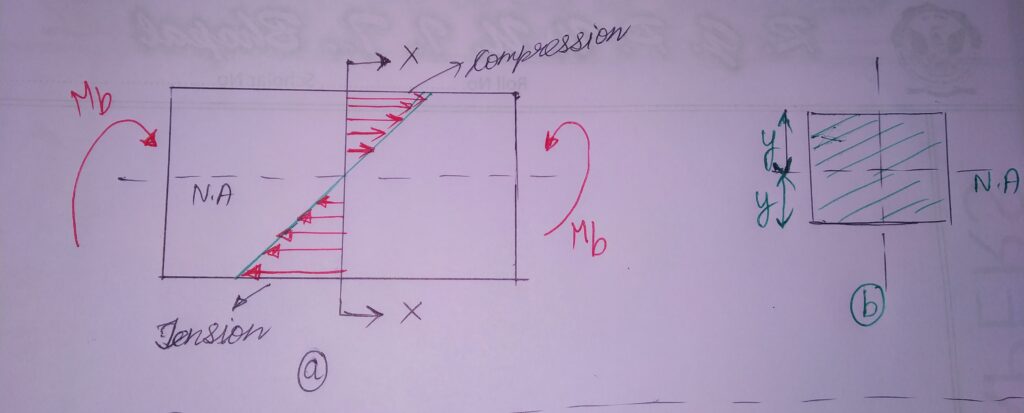
As seen from the diagram;
We observe that the beam experiences a tensile stress on one side of Neutral Axis(N.A) and as well as a compressive stress on the other side of N.A whose distribution is shown above.
In practical view, Cracks appear on the outer surface as well as folds in the inner layers of element.
ASSUMPTIONS IN ANALYSIS:
1.Beam is straight with uniform cross section.
2.Forces acting on beam lie in plane perpendicular to the beam axis.
3. Material is homogeneous, isotropic as well as obeys Hooke’s law.
4. Plane cross section remain plane even after bending.
CONSIDER a fibre element section XX whose extreme layer is at a distance y from the neutral axis (N.A) in above diagram.
NEUTRAL AXIS (N.A) = The axis on which the resultant bending moment (B.M) is zero.
The bending stress at any fibre at a distance y from neutral axis is :
σb = Mb y /I (Equation 1 )
where , σb=Bending stress because of moment at a distance y from N.A (N-mm2/MPa)
Mb = Applied bending moment (N-mm)
I = Moment of inertia of the cross section about neutral axis (mm4)
# (σb)max. occurs at y= ymax.
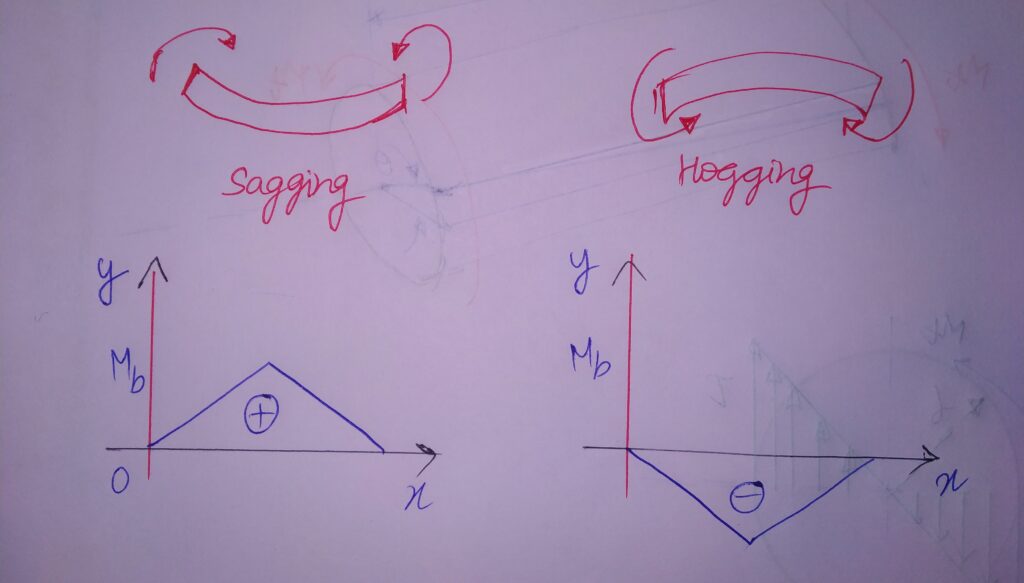
# From Equation 1 , σb ∝ y ; therefore ,the characteristic graph will be linear ( with slope = Mb/I ).
AREA MOMENT OF INERTIA (I) :
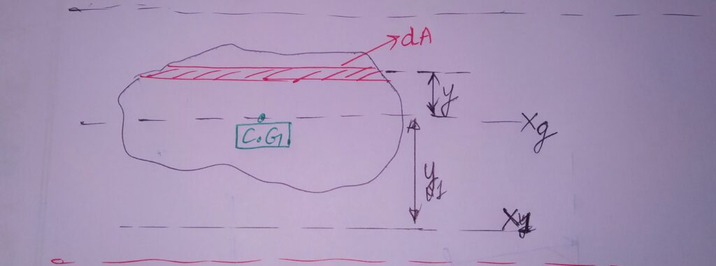
a)FOR a General cross section area, The Area MOI (I) about the centroidal axis Xg is given by :
IXg= ∫y2 dA
b) MOI of the Area about X1 ( an axis at a distance y1 from Xg as well as parallel to it)
Ix1= IXg + Ay12 A= area of cross section
ANALYSIS OF B.M :
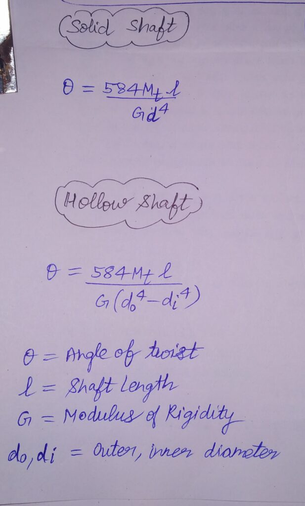
3. STRESSES DUE TO TORSIONAL MOMENT:
Consider a transmission shaft on which an external torque is applied of magnitude Mt.
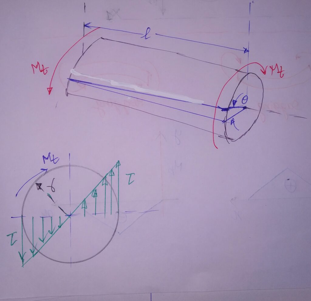
Due to this, twisting occurs which causes internal resisting stresses. These stresses are therefore called Torsional shear stresses.
ASSUMPTIONS IN ANALYSIS :
1. Shaft is straight with a uniform circular cross section.
2. Plane transverse section maintains planarity even after torsion.
3.Material is homogeneous, isotropic as well as obeys Hooke’s law.
The torsional shear stress on a shaft is given by :
τ = Mt r /J (equation 2)
where , σb=Torsional shear stress because of torsion (N-mm2/MPa)
Mt = Applied torque/ torsional moment (N-mm)
J = Polar Moment of inertia of the cross section about rotation axis (mm4)
POLAR MOMENT OF INERTIA (J):
SOLID SHAFT : J = Πd4/32
HOLLOW SHAFT : J= Π (do4– dI4)/32


