
Institute in Pune, Maharashtra
Authors : Bhavesh Bedse , Ayush Bhakkad , Vedant Bharuka, Sarang Deshpande, Raj Gharate
Guide : Prof. Avdhoot Rajurkar
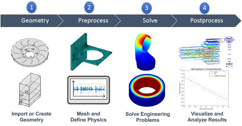
Computer-aided engineering (CAE) is the practice of using computer software to analyze and test engineering products virtually. You can simulate, validate, and optimize products using a CAE tool based on the results of a numerical analysis. For a wide range of industries, computer-aided engineering (CAE) is the use of computer software to simulate performance in order to improve product designs or assist in the resolution of engineering challenges. Simulation, validation, and optimization of goods, processes, and production tools are all part of this.
Engineers model the geometry (or a system representation) and physical qualities of the design, as well as the environment in the form of imposed loads or constraints, during the preprocessing step.
The model is then solved using a mathematical representation of the underlying physics. The results are submitted to the engineer for assessment during the post-processing phase.
CAE solutions are utilized in a variety of sectors to assess component and assembly robustness and improve performance. At the same time, engineering simulation is a critical tool for product optimization for design teams.
For design engineers, CAD and CAE integration has become a crucial element of their day-to-day process. Using the SaaS versions of both products can help to bridge the gap, allowing engineers to quickly create CAD models and execute engineering simulations.
Types of CAE Analysis
Finite element analysis (FEA)
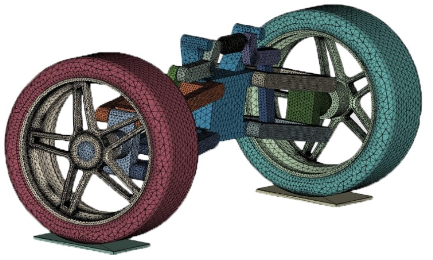
The act of modeling the behavior of a part or assembly under specified conditions in order to examine it using the finite element method is known as finite element analysis (FEA) (FEM). FEA is a method of understanding and quantifying the impacts of real-world conditions on a part or assembly using mathematical models. Engineers can use these simulations, which are run using specialized software, to find possible flaws in a design, such as areas of tension and weak spots.

It is possible to comprehend and quantify structural or fluid behavior, wave propagation, heat transport, and other processes using mathematics.
Calculations, models, and simulations are used in finite element analysis (FEA) to anticipate and understand how an item will respond under various physical conditions. Engineers utilise finite element analysis (FEA) to detect flaws in their design prototypes.
FEA employs the finite element method (FEM), a numerical methodology that divides an object’s structure into several components, or elements, and then links them at nodes. Engineers, developers, and other designers can utilize the FEM to do finite element analysis since it generates a set of algebraic equations.
The majority of processes can be represented with partial differential equations (PDEs), however these complicated equations must be solved in order to determine parameters like stress and strain rates. The use of FEA allows for a rough answer to these issues.
Modern software simulation software is built on the basis of FEA, with the findings being shown on a computer-generated color scale.
While some hypotheses claim that FEA originated with Euler’s work in the 16th century, the first mathematical papers directly describing the technique came from Schellbach’s work in 1851.
Engineers from various industries around the world continued to develop FEA in order to tackle a wide range of structural mechanics problems, particularly in civil engineering and aerospace. FEA for real-world applications was originally created in the mid-1950s, and it was progressively developed throughout the next few decades.
How Does Finite Element Analysis Work? Click here
FEA simulations are made up of a mesh of millions of tiny pieces that combine to form the geometry of the structure under consideration. Each of these minor pieces is calculated separately, with the mesh refinements combining to generate the overall structure’s ultimate output.
These approximation calculations are typically polynomial in nature, with interpolations occurring across the small elements, allowing values to be established at some but not all places. The sites where the values may be determined are known as nodal points, and they are frequently situated near the element’s boundary.
Types of FEA tests
Structural static analysis:
This sort of FEA examines a proportionally scaled model. Any structure that is sound on a small scale will be able to manage the same interactions with the full-size structure and generate the same results, according to the test.
Thermal engineering analysis:
This experiment looks at how temperature changes affect the design structure.
Modal analysis:
As everything vibrates at a certain frequency, modal analysis should be used to see how disruptive external vibrations affect the product’s structure. This type of finite element analysis also enables users to account for vibrations throughout the design process, resulting in a more durable end product.
The basics of finite element analysis involve boundary conditions like forces and pressures, as well as three governing equations:
Principles of FEA
Equilibrium equations determine when opposing forces or effects are in equilibrium.
Strain-displacement relationships, which quantify the deformation that a design undergoes as a result of external forces.
Constitutive equations are mathematical relationships between two physical characteristics that are particular to a metal or substance and indicate how the material will react to external stimuli.
Advantages of FEA
Increased precision as a result of the examination of any physical stress that could damage the design.
Developers can see how stresses in one element affect the materials in another related element, resulting in better design.
Testing at an earlier stage in the development process. Instead of the days or weeks it takes to make physical prototypes, virtual prototyping allows the designer to simulate multiple designs and materials in a couple of hours.
FEA software allows developers to generate higher-quality products in a quicker design cycle while utilizing less material, resulting in increased productivity and income.
As a result of being able to model both the interior and exterior of the design, you'll have a better understanding of key design parameters.
Models are used more efficiently since one model can be used to test multiple failure scenarios or physical events.
Calculation times are quick, and investment expenses are modest.
Existing experimental data can be retrieved from parametric analyses of previously validated models and used in the new model.
Common applications of FEA
In mechanical, aerospace, automotive, and civil engineering applications, as well as biomechanics, FEA is extensively employed. It’s crucial for designing machines, analyzing machine and part fatigue, certifying load capacities for lifting cranes, constructing airport bridges, and determining brake or rotor lifetime certifications, among other things.
• Improving the safety of products
• Putting the concept through its paces in real-world scenarios
• lowering the cost of design and production
• Alternative designs and materials are being evaluated and optimized.
• Quickly analyzing many basic answers
• Obtaining recognition and credit for a product or firm from nationally and internationally recognised certification authorities
• Optimizing workstation and personal computer operations.
Computational fluid dynamics (CFD) Click here
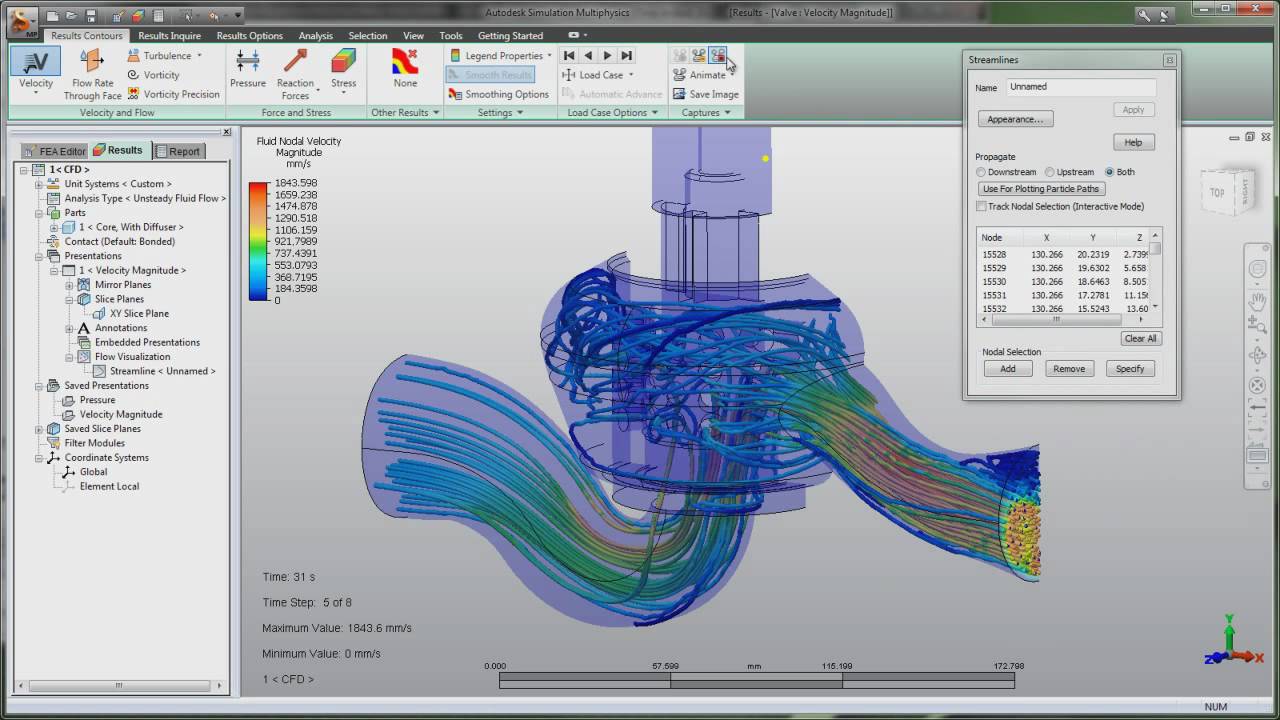
Computational fluid dynamics (CFD) is a branch of fluid mechanics that analyses and solves problems involving fluid flows using numerical analysis and data structures. It is the science of numerically resolving a set of governing mathematical equations: conservation of mass, momentum, energy, and species mass to forecast fluid flow, heat and mass transport, chemical processes, and other phenomena. It is a vital instrument in fluid mechanics that uses numerical methods and algorithms to solve and evaluate problems involving fluid flow. The calculations necessary to model the free-stream flow of the fluid and the interaction of the fluid (liquids and gases) with surfaces defined by boundary conditions are performed using computers. Better answers can be achieved with high-speed supercomputers, which are frequently required to handle the largest and most complicated issues. Current research is yielding software that increases the accuracy and speed of difficult simulation scenarios like transonic or turbulent flows.
Approximations that solve partial differential equations (PDEs) regulating flows have been used to forecast the behavior of fluid flow using CFD. The technique for establishing the degree to which the CFD model is an accurate depiction of the real world from the perspective of the predicted application is critical for its effectiveness.

Typically, experimental apparatus like wind tunnels are used to perform initial validation of such software. Furthermore, a previously completed analytical or empirical investigation of a certain subject can be compared. Full-scale testing, such as flight tests, is frequently used for ultimate confirmation.
Aerodynamics and aerospace analysis, hypersonics, weather simulation, natural science and environmental engineering, industrial system design and analysis, biological engineering, fluid flows and heat transfer, engine and combustion analysis, and visual effects for film and games are just a few of the fields and industries where CFD is used.
The Navier-Stokes equations, which study single-phase fluid flows, are at the heart of CFD. Scientists and engineers have been employing these equations to address fluid issues since the early 1930s, but due to a lack of computational capacity, they were simplified and reduced to two dimensions.
These early practical uses of fluid dynamic analysis, while basic, paved the way for what would soon become an indispensable simulation element.
Solving CFD difficulties involved simplifying equations to the point that they could be done by hand for the majority of the early years. CFD was essentially a theoretical and exploratory discipline until the late 1950s, therefore the average engineer was not employing these calculations.
CFD analysis has a long history in the business, with many famous names developing it into one of the most powerful simulation tools available.
Understanding the sophisticated mathematics behind CFD isn’t required for many modern engineers to do simulations. The tools are not just used by professionals in fluid dynamics and mathematics, but they can now be used by any engineer, regardless of their ability level.
Boundary element method (BEM)
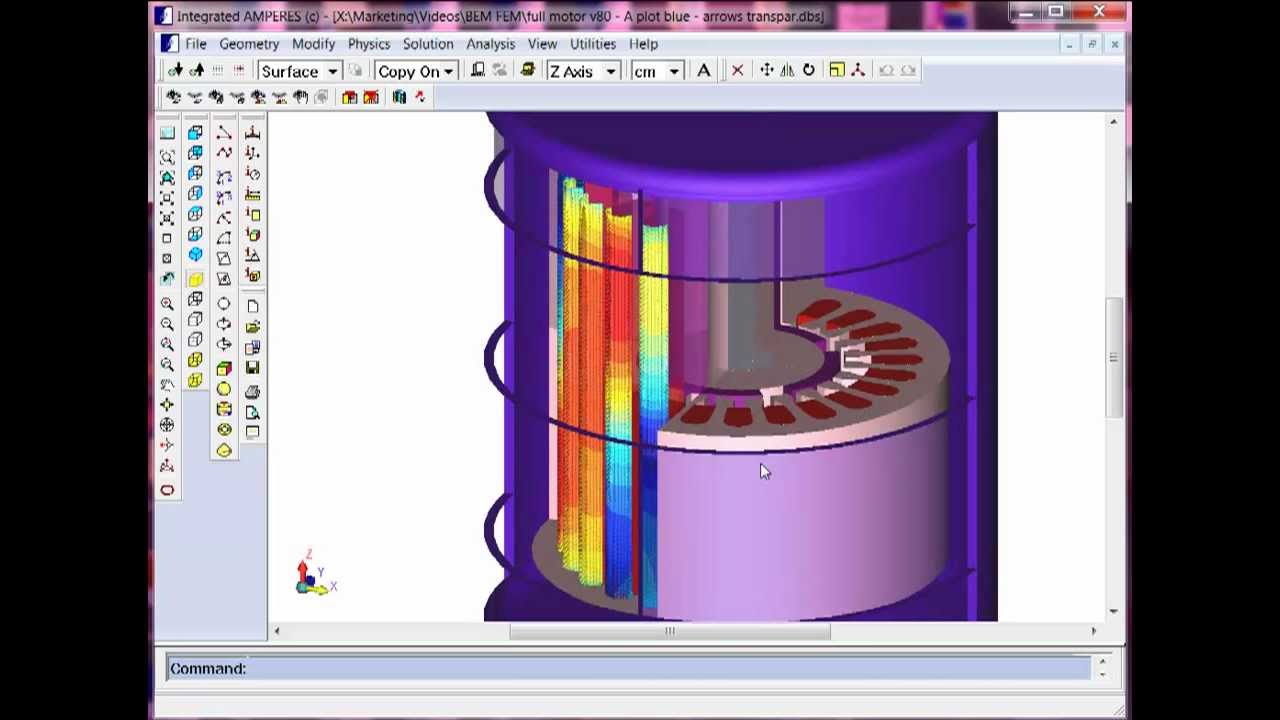
The boundary element method (BEM) is a numerical computational method for solving linear partial differential equations that have been formulated as integral equations (i.e. in boundary integral form), such as fluid mechanics, acoustics, electromagnetics, fracture mechanics, and contact mechanics.
Engineering issues involving differential equations are solved using the boundary element method. Because it is effective at addressing boundary value issues, BEM is also known as the boundary integral equation method (BIEM). BEM is a numerical method for solving boundary integral equations and other physical problems with intricate boundaries that is superior to other numerical methods.
![PDF] The coupling finite-boundary element method for soil-structure interaction under spatially varying ground motion | Semantic Scholar](https://d3i71xaburhd42.cloudfront.net/1e13e445d114a2e6407e6608e84f068c20b58973/5-Figure2-1.png)
Electrical machines, actuators, antennas, waveguides, actuators, and other electromagnetic challenges can all benefit from BEM. BEM only requires discretization on the surface of a body, which reduces the amount of data needed to analyze and solve the problem. Because it uses discontinuous components to produce surface mesh, BEM is a versatile numerical approach. It also delivers highly accurate answers achieved through the use of boundary elements.
Advantages of the Boundary Element Method
The numerical procedure is made easier by boundary discretization.
For 3D challenges, mesh generation is easy in BEM.
Because BEM is a semi-analytical method, it achieves high accuracy.
Open border and moving boundary situations are also suitable.
BEM can be used in conjunction with analytical and numerical approaches like FEM.
Applications of CAE
• Finite element analysis is used to analyse stress and motion on components and assemblies (FEA)
• Computational fluid dynamics is used to perform thermal and fluid analyses (CFD)
• Mechanism kinematics and dynamic analysis (multibody dynamics)
• FEA or the boundary element approach are used to analyse acoustics (BEM)
• For multi-domain mechatronics system design, 1D CAE, or mechatronic system simulation, is used.
• Simulation of mechanical events (MES)
• Analysis of control systems
• Manufacturing operations like as casting, moulding, and die press shaping can all be simulated.
• Improvements to the product or process