


ENDURANCE LIMIT AND FATIGUE LIFE : WHY IT IS IMPORTANT?
ENDURANCE LIMIT : INTODUCTION
In the previous blog, we saw what we meant by fatigue loading. And also learned about its types, as well as its action and effect on a machine element.
Observations concluded that component fails at a stress below the yield or ultimate strength of a material in fatigue loading.
Therefore, it became important to find out the limiting or permissible max. stress so that safe design can be done.
So, a term coined by engineers in design known as ENDURANCE LIMIT/FATIGUE LIMIT.
ENDURANCE/FATIGUE LIMIT : DEFINITION
The maximum stress amplitude of a completely reversed stress that a standard specimen can sustain for an unlimited no of cycles without fatigue failure.
Since, unlimited no. of cycles seems impossible in real , therefore, we take 106 cycles as standard.
106 cycles OR 1 million cycles are just sufficient for defining endurance limit.
A term parallely studied with Endurance Limit is Fatigue Life.
FATIGUE LIFE: DEFINITION
The no of stress cycles that the standard specimen can complete during the test before the appearance of first fatigue crack.
FINDING ENDURANCE LIMIT : THE “R.R.MOORE” PRACTICAL APPROACH
As we know that fatigue failure is multi step failure process . To know more about fatigue failure process, refer to the blog link given below:
http://mechomotive.com/wp-admin/post.php?post=3674&action=edit
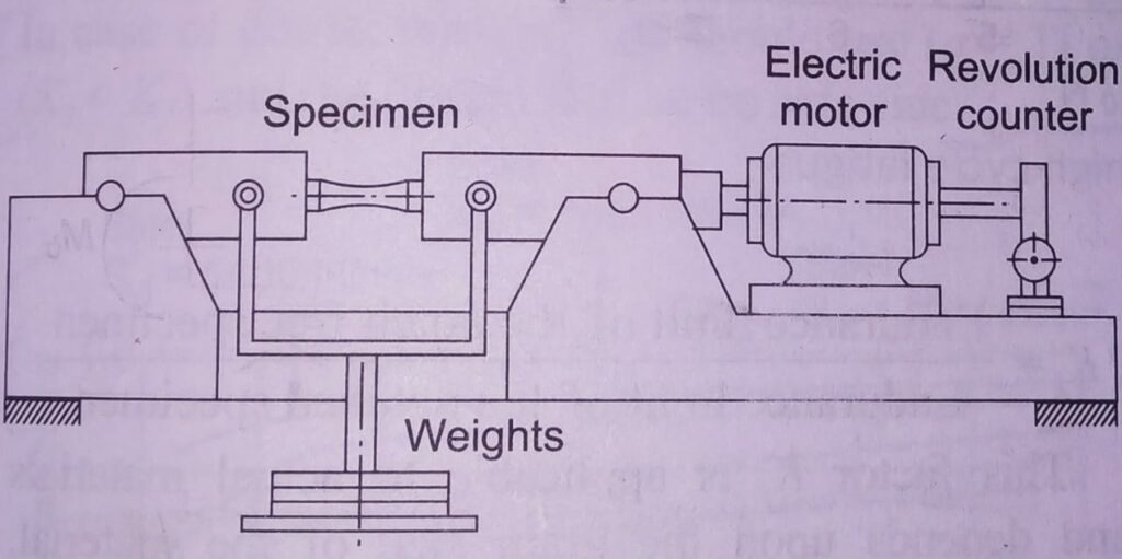
So, to find its value , a machine called Rotating Beam Fatigue Testing Machine came in light made by R.R.MOORE .
EXPERIMENT:
A specimen beam taken with following dimensions.
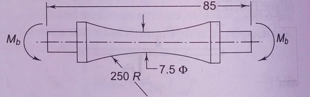
First of all, the specimen well machined and polished finishing ; as well as final polishing done in axial direction to avoid circumferential scratches.
The specimen then made to rotate by an electric motor after fixing it on the testing machine.
CONCEPT:
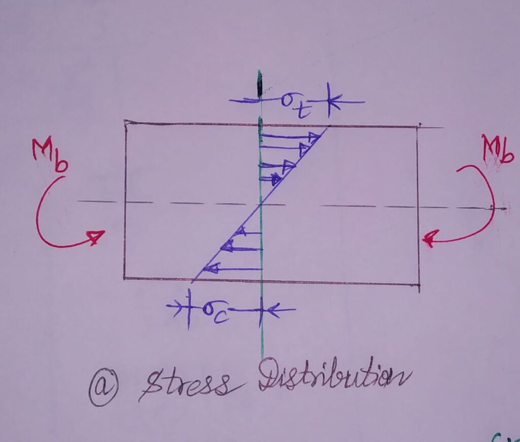
Then ,a bending moment Mb induces on the beam. Due to this, tensile and compressive stresses induces on the upper and lower halves of beam respectively. While, the central plane along the Neutral Axis remains plane intact due to zero stress.
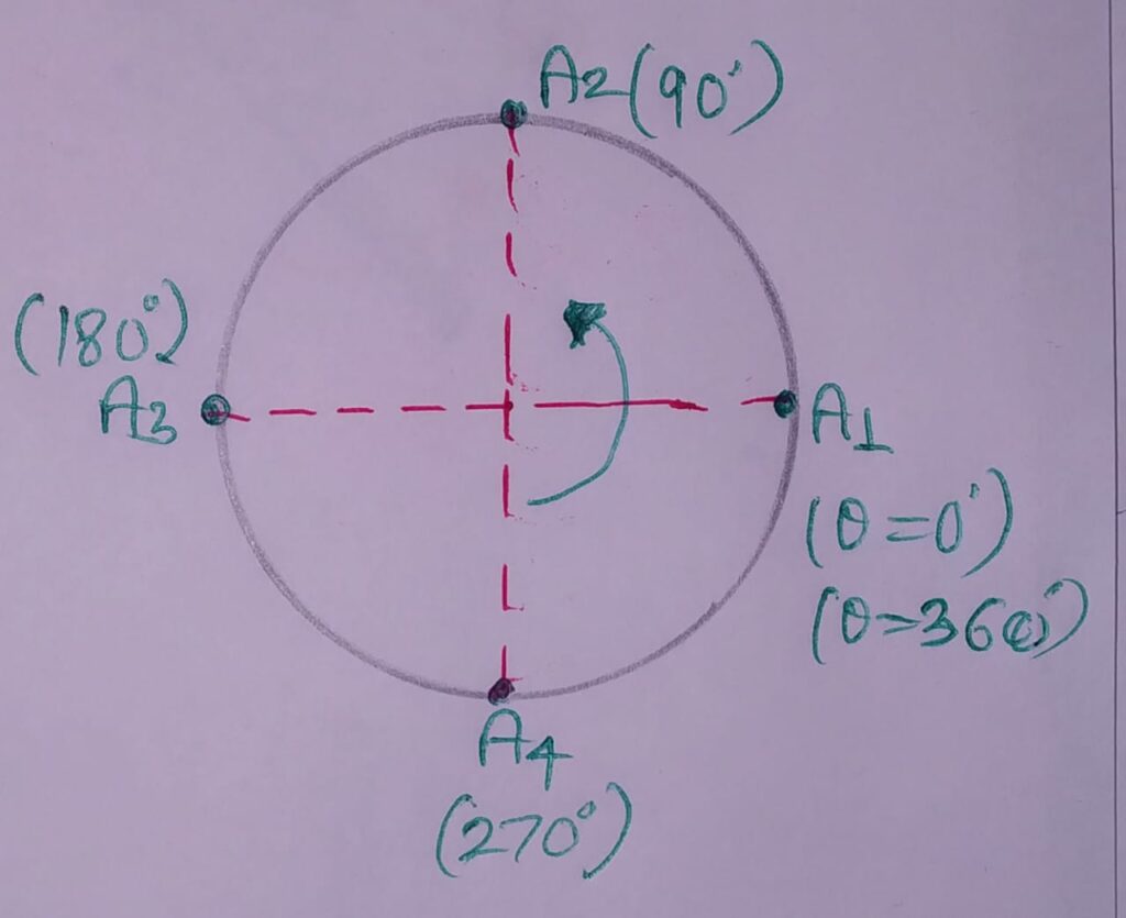
Lets consider a point A on the beam surface.
Now, whole analysis will be based on point A.
Analysis : to find State of A at every shaft rotation (θ= 0 TO 360)
STATE 1 : (AT θ=00): Point A1 on the beam surface along Neutral Axis . Here, the stress is zero in the central plane.
STATE 2 : (AT θ=900): Point A2 on the beam perpendicular to the Neutral Axis in the upper zone of beam. Here, tensile stresses induces in the shaft upper portion. Therefore, max. tensile stress is in this position, denoted by σt.
STATE 3 : (AT θ=1800): Point A3 on the beam surface along Neutral Axis opposite to Point A1 .Here, the stress is zero in the central plane.
STATE 4 : (AT θ=2700): Point A4 on the beam perpendicular to the Neutral Axis in the lower zone of beam. Here, compressive stresses induces in the shaft upper portion. Therefore, max. compressive stress is in this position, denoted by σc.
OBSERVATION:
The beam subjected to completely reversed stresses during one cycle i.e Tensile stresses in the first half and compressive stresses in the second half. Also, distribution is sinusoidal and one stress cycle completed in one revolution.
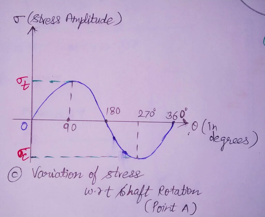
The amplitude of this stress is given by :
σt or σc = Mb y /I
PRACTICAL ANALYSIS:
During practical, the no of revolutions are noted from a revolution counter before the first crack appears. In each test, there are two values taken;
1. Stress amplitude (Sf)
2. No of stress cycles(N)
A graph is plotted between these two values , which comes out to be the S-N CURVE.

