EQUATIONS INVOLVING HELICAL SPRINGS(COMPR./EXT.) DESIGN :
Equations came in derivation from many corners of the world ; so that Helical Springs’ Design can be done.
From the following, two equations came in selection, namely :
1) LOAD-STRESS EQUATION
2) LOAD-DEFLECTION EQUATION
ANALYSIS ,STUDY AND OBSERVATIONS
Consider a helical spring that is made from circular cross section wire as shown.
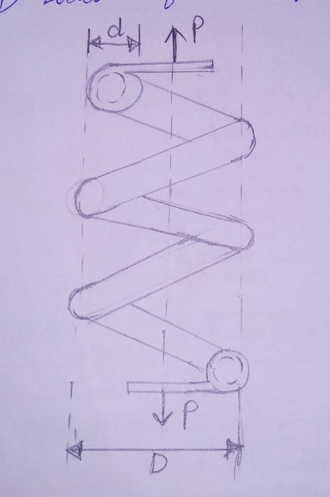
Here, D and d are Mean coil diameter and wire diameter respectively.
No. of active coils in the spring=N ;
and the spring subjected to Axial force =P
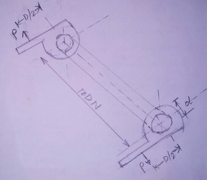
Now, let’s uncoil this spring and straighten it in linear direction. Therefore, it takes the shape of a bar as shown below.
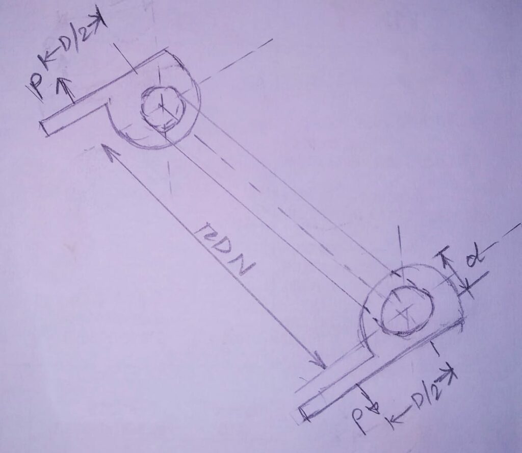
In this analogy, stress equation derived for the bar to be taken equivalent to the actual helical spring.
DIMENSIONS OF EQUIVALENT BAR:
1. The diameter of the bar always taken equal to the Wire diameter of the spring (d).
2. We know; length of one coil in the spring= πD. And ,we have N active coils. Therefore, length of equivalent bar = πDN
3.The bar equipped with brackets on either ends. The length of this bracket equal to the Mean coil radius of spring (D/2).
ANALYSIS (BASIC):
A) RELATION BETWEEN STRESS AND LOAD :
**Force P acts at the bracket end , due to which Torsional shear stress induces in the bar. Torsional Moment(Mt) given by; Mt=P.D/2
Therefore; Torsional shear stresses (τ1) on the bar given by;
τ1=16 Mt/πd3= 16 /πd3 {P.D/2}=8PD/πd3 —————- Eq.1
During uncoiling of spring and converting it to a bar , additional stresses are induced in the system due to following two factors:
1) Presence of direct or transverse shear stress in the spring wire.
2)During the bending of bar in the form of a coil, the length of inner fibres are less than the length of outside fibres ;which leads to stress concentration.
In practical study, the Resultant stress developed in the spring consists of Superimposition of Torsional shear stress, direct shear stress , and additional stresses occurring due to curvature of the coil.
The Stress Distribution under various conditions have been shown below:
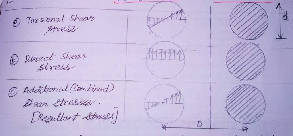
The Eq.1 calculated above was derived on the assumption that there is no effect of Direct Shear Stress and Stress Concentration due to coil curvature.
ANALYSIS (CONSIDERING OTHER STRESS EFFECTS):
Now, Considering these stress effects , we define two assumed factors , namely Ks and Kc.
Ks = Factor to account for Direct Shear Stress
Kc = Factor to account for Stress Concentration due to coil curvature.
*COMBINED EFFECT OF THESE TWO FACTORS GIVES K=Ks.Kc Where, K= Factor on account for combined effect.
** Let Direct Shear Stress= τ2
τ2=P/A = P/(πd2/4)=4P/πd2
τ2=8PD/πd3(0.5d/D)
Therefore,
τtotal= τ1+ τ2
=8PD/πd3+ 8PD/πd3(0.5d/D)
=8PD/πd3{1+(0.5d/D)}
where, 1+(0.5d/D)= Ks =Shear stress concentration factor
Ks= 1+(0.5d/D)=1+(0.5/C)
Therefore , equation now becomes as:
τ= 8PD/πd3{Ks}
This Equation was later experimentally verified by A.M.WAHL. Therefore equation now becomes:
τ= 8PD/πd3{K} K= Stress factor/Wahl Factor
This Equation Came to be known as the LOAD STRESS EQUATION.
K=(4C-1)/(4C-4) + 0.615 /C where , C= D/d= spring index
#When Spring subjected to fluctuating stresses ; Ks and Kc are separately used in the equation.
B)RELATION BETWEEN STRESS AND DEFLECTION :
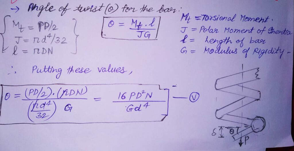
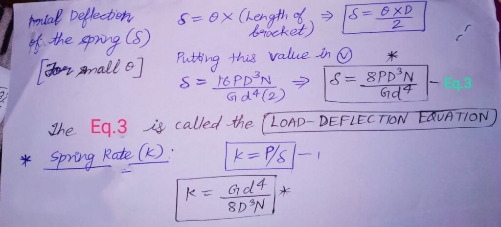
This Eq.3 is called LOAD DEFLECTION EQUATION.
VARIATION OF SPRING PARAMETERS:
#When a spring is cut into 2 parts ; following observed changes in the equations ;
1.Parameters G, d and D remains same.
2.N becomes N/2.
3.Stiffness (k) becomes 2k.
ANALYSIS OF STRAIN ENERGY IN SPRINGS:
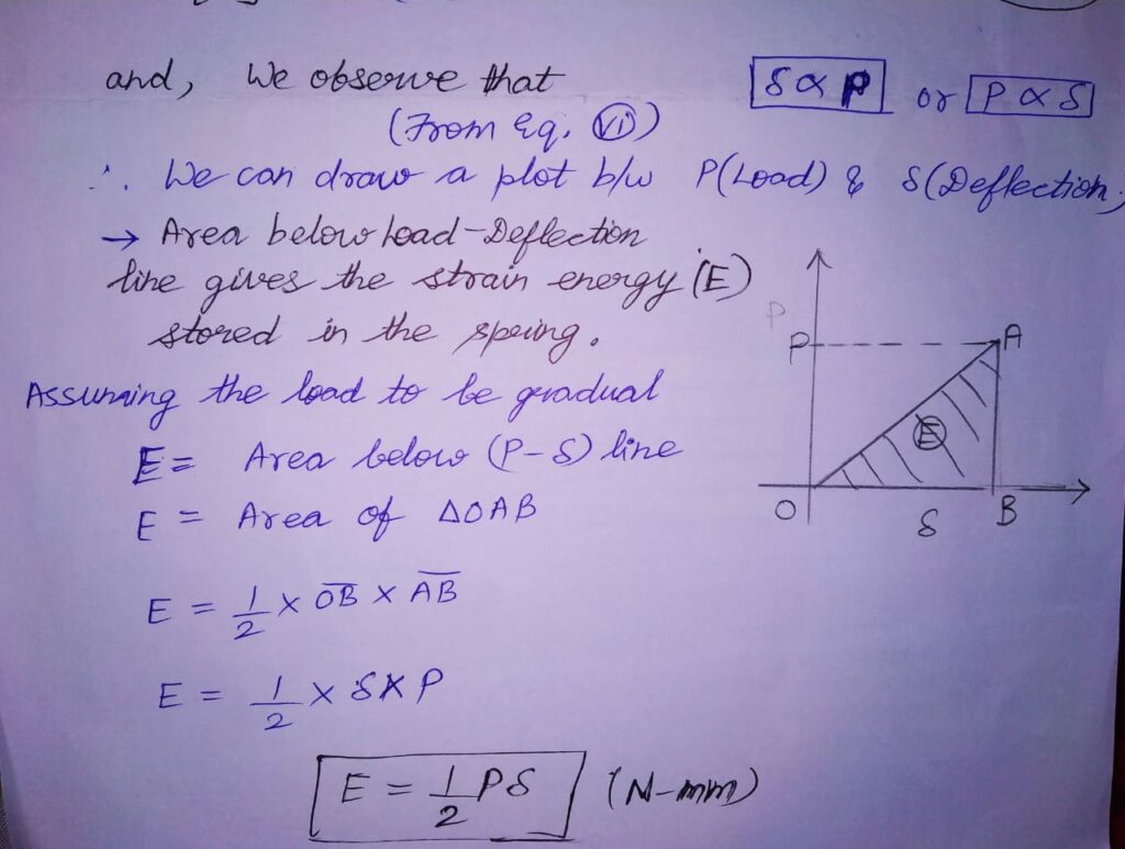
As observes from Eq.3 , we can draw a plot between Load(P) and Deflection(δ).
