


STRESSES AND DESIGN ANALYSIS: HOW THE PROCESS OCCURS?????????
Reversed stresses : Those stresses which have same magnitude of stresses but in opposite sense (i.e σ1 = -σ2).
Here, σm=0 & σv = σ1 or σ2
Fluctuating stresses : Those stresses which have different magnitude of stresses and also induces in a specific direction.
σm= σ1 +σ2/2 & σv = σ1 – σ2/2 where , σ1= maximum stress σ2= minimum stress
In fatigue design , we deal with two types are problems:
1) Components subjected to completely reversed stresses
2) Components subjected to fluctuating loading stresses
For reversed stresses ,since the Mean stress value is zero.
Therefore tensile stresses occupy the first half and Compressive stresses occupy the second half of the stress distribution.
Whereas, for fluctuating loading stresses, there comes a definite non zero mean stress value.
Therefore, the stresses here can be purely tensile, purely compressive or Mix of both tensile and compressive.
DESIGN STRATEGY FOR REVERSED STRESS PROBLEMS:
For designing a component subjected to completely reversed stresses, there are further 2 sub conditions under which study is done.
1) DESIGN FOR INFINITE LIFE
2) DESIGN FOR FINITE LIFE
DESIGN FOR INFINITE LIFE
When a component has to be designed for infinite life, the ENDURANCE LIMIT becomes the failure criteria. Here, the stress amplitude (σf) should be less than the Endurance Limit (σe) to withstand infinite no. of cycles.
These equations are mainly used in this type of design analysis:
σa=Se / FOS τa = Sse / FOS
Where ;
σa = Stress amplitude in component (due to bending)
Se = Corrected Endurance Limit in reversed bending
τa = Stress amplitude in component (due to torsion)
Sse= Corrected Endurance Limit in reversed bending
DESIGN FOR FINITE LIFE
When a component has to be designed for finite life, the S N CURVE becomes the failure criteria. Here, the stress amplitude (σf) is usually greater than the Endurance Limit (σe). It mostly finds applications in steels.
PLOTTING TECHNIQUE OF S N CURVE :
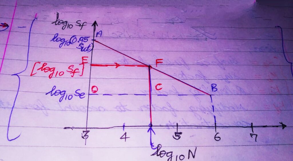
THE S N CURVE drawn here is a Straight Line AB drawn from (0.9 Sut) at 103 cycles to Se at 106 cycles on a LOG-LOG graph paper.
PLOTTING PROCEDURE :
1. Locate point A with coordinates {log10(103),log10(0.9 Sut)}= {3, log10(0.9 Sut)} .
2. Locate point B with coordinates {log10(106),log10(Se)}= {6, log10(Se)} .
3.Join AB . This is the criterion for failure for Finite life problems.
4. Depending upon the Value of the life N given to us, draw a vertical line passing through log10N on the abscissa, which further intersects AB at point F.
5. Draw a line FE parallel to abscissa. The ordinate at point E i.e log10Sf gives the fatigue strength corresponding to N cycles.

