


ECCENTRIC LOADING,STIFFNESS AND DESIGN-IT’S SIGNIFICANCE
ECCENTRIC LOADING CONDITIONS AND STIFFNESS PLAYS AN IMPORTANT ROLE IN DESIGN ANALYSIS AND STUDY.
Stiffness defined as the ability of a material to resist deformation/deflection due to under external loading.
Within elastic limit, deformation is inversely proportional to stiffness,
i.e. for less deformation, a given material is the stiffest AND Vice Versa.
When dealing in stiffness criteria, permissible deformation is the criteria of design.
Modulus of elasticity is a measuring criterion for stiffness of a machine element.
CONSIDER A SHAFT SUPPORTING A GEAR. This shaft undergoes a deflection.
Gear teeth meshing disturbs due to excess Shaft deflection. Gear’s face width gets uneven load distribution causing early material failure. Shaft’s deflection causes axes misalignment, wearing of bearing and other machine parts.
So, in practical study , stiffness plays an important role in designing structural analysis.
DEFINITION :
Defined as the force required so that it produce unit deflection. Denoted by k.
k = P/ δ
Where, k = Stiffness due to force P(N/mm)
P = force (N)
δ = Deflection due to force P
STIFFNESS(k) IN VARIOUS CASES:
1.AXIAL LOADING :
Deflection due to force P given by : δ = Pl/AE
Therefore, k = P/δ =AE/l
where, k=Axial stiffness(N/mm) A= Cross sectional area of rod (mm2)
E= Modulus of elasticity (N/mm2)
l= Length of rod (mm)
FOR SHAFT : Deflection due to torsion Mt , causing angle of twist ( θ ) , angle of twist given by-: θ =584Mt l/Gd4
Therefore , k= Mt /θ =Gd4/584l
where, k= Torsional stiffness (N-mm?deg)
d= Shaft diameter (mm)
l= Length of shaft (mm)
G= Modulus of rigidity (N/mm2)
3. BEAMS UNDER LOAD :
A) Cantilever beam :
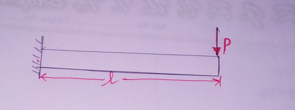
Deflection due to load P = δ = Pl3 /3EI P= Load applied at the beam end
Stiffness in the beam : k= P/δ= 3EI/l3
B)Simply Supported Beam:
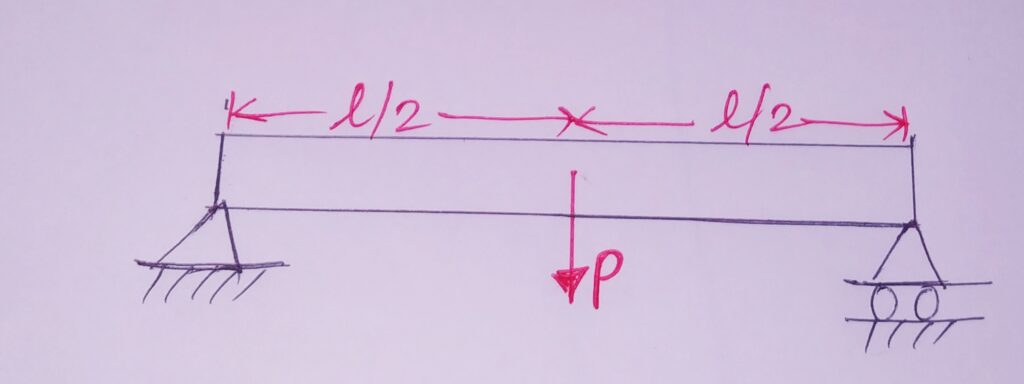
Deflection due to load P = δ = Pl3 /48EI P= Load applied at the centre of beam
Stiffness in the beam : k= P/δ= 48EI/l3
STRAIN ENERGY ( TENSION, BENDING AND TORSION)
When load applied to a machine component, material deforms due to the load. The work dine in this process is converted to strain energy stored in the machine component.
Energy induced or work done by the load in a loaded body.
Here , energy gains or losses due to heat are considered negligible.
Denoted by U.
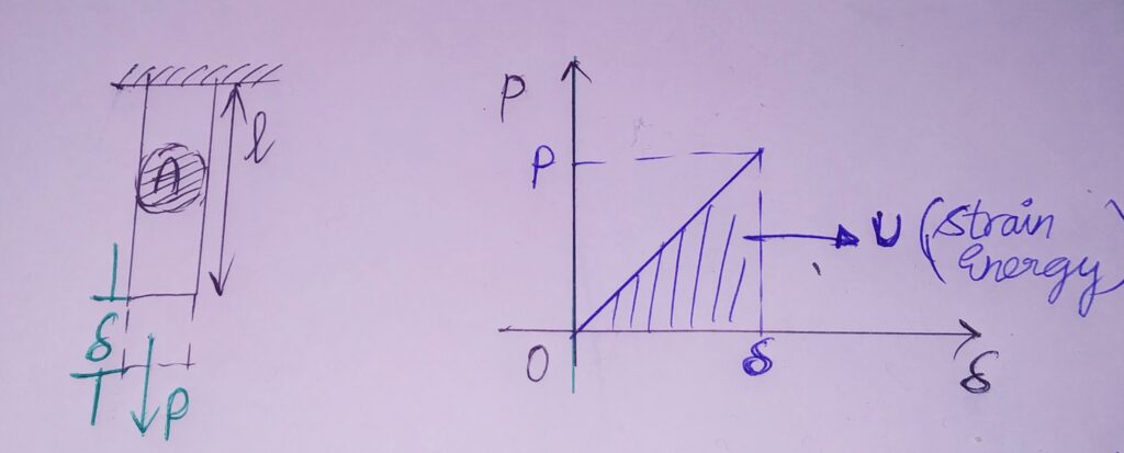
U= Pδ/2 U/volume = σε/2
1.TENSION:
U= P2l/2AE
2. BENDING (FOR BEAMS)
U = ∫ Mb2 dx /2EI
3. TORSION(FOR SHAFT)
U = Mt2l /2GJ
ECCENTRIC AXIAL LOADING
Defined as that type of loading in which Load acts along the axis of element , but not through the centroid of the element.
Here, it acts at an eccentric distance from the centroidal axis.
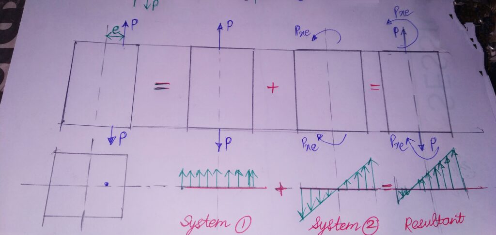
ACCORDING TO STATICS :
This force system can , therefore be analysed as a combination of two loading systems
1.System with load P acting on the centroidal axis.
2.System with a couple (P*e) acting due to Load P.
System 1 will produce a stress equal to σ1=P/A ,while System 2 will produce a bending stress of magnitude σ2=Pey/l
Resultant stress of the compound system = Superimposition of System (1+2)
σresultant=σ1+σ2=σ2=P/A ± Pey/l
The stress distribution is shown below:

