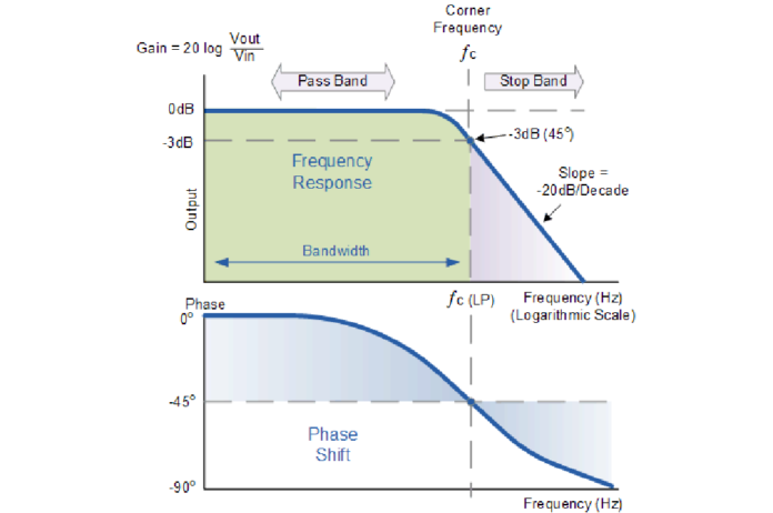
Low-pass filter is a filter that passes signals with a frequency lower than a selected cutoff frequency and attenuates signals with frequencies higher than the cutoff frequency. The exact frequency response of the filter depends on the filter design. The filter is sometimes called a high-cut filter, or treble-cut filter in audio applications. A low-pass filter is the complement of a high-pass filter.
In optics, high-pass and low-pass may have different meanings, depending on whether referring to frequency or wavelength of light, since these variables are inversely related. High-pass frequency filters would act as low-pass wavelength filters, and vice versa. For this reason it is a good practice to refer to wavelength filters as short-pass and long-pass to avoid confusion, which would correspond to high-pass and low-pass frequencies.
Low-pass filters exist in many different forms, including electronic circuits such as a hiss filter used in audio, anti-aliasing filters for conditioning signals prior to analog-to-digital conversion, digital filters for smoothing sets of data, acoustic barriers, blurring of images, and so on. The moving average operation used in fields such as finance is a particular kind of low-pass filter, and can be analyzed with the same signal processing techniques as are used for other low-pass filters. Low-pass filters provide a smoother form of a signal, removing the short-term fluctuations and leaving the longer-term trend.
Filter designers will often use the low-pass form as a prototype filter. That is, a filter with unity bandwidth and impedance. The desired filter is obtained from the prototype by scaling for the desired bandwidth and impedance and transforming into the desired band-form (that is low-pass, high-pass, band-pass or band-stop).
What is the use of low pass filter?
Low pass filters are used to filter noise from a circuit. ‘Noise’ is a high frequency signal. When passed through a low pass filter most of the noise is removed and a clear sound is produced.
Do low pass filters have gain?
While this configuration provides good stability to the filter, its main disadvantage is that it has no voltage gain above one. However, although the voltage gain is unity the power gain is very high as its output impedance is much lower than its input impedance.
What should I set my low pass filter to?
As a general rule, the Low-Pass Filter should set at a value approximately equal to (or below) 70% of your main speaker’s lowest frequency response. For example, your speaker’s frequency response goes down to 43Hz. 70% of 43Hz equals 30.1, so you should set the subwoofer’s low pass filter to 30Hz.
What is RL low pass filter?
The inductor allows the low-frequency signal to pass which eventually establishes across the resistor and it blocks high-frequency signal which does not make it to the load resistor. Inductor provides low reactance for low-frequency signal & high reactance for a high-frequency signal.
What are the components of a low pass filter?
The simplest low pass filters consist of a resistor and capacitor but more sophisticated low pass filters have a combination of series inductors and parallel capacitors. In this tutorial we will look at the simplest type, a passive two component RC low pass filter.
What Hz is best for bass?
The fundamental notes of rhythm are center on this area. Most bass signals in modern music tracks lie around the 90-200 Hz area. The frequencies around 250 Hz can add a feeling of warmth to the bass without loss of definition. Too much boost in the bass region tends to make the music sound boomy.
How do you set a low-pass filter on a subwoofer?
- Select [Setup] – [Audio Settings] from the home menu.
- Select [Subwoofer Low Pass Filter].
- Then setting you want. On: Always activates the low-pass filter with a cutoff frequency of 120 Hz. Off: Does not activate the low-pass filter.
How do you test a low-pass filter?
When testing a low-pass filter, generally you have to use an arbitrary waveform generator (Arb). To create test tones to pass through the filter to measure the relative gain. Or attenuation of each tone to find the cutoff frequency of the filter.
How do we calculate low-pass filter bandwidth?
If you consider an ideal low-pass filter with cut-off frequency of fc, all frequencies greater than fc will be removed. Then it’s bandwidth is equal to fc-Hz (from 0 up to fc). The total bandwidth BT is simply twice that: BT=2fc. Since we are also considering negative frequencies, from −fc up to fc.


